
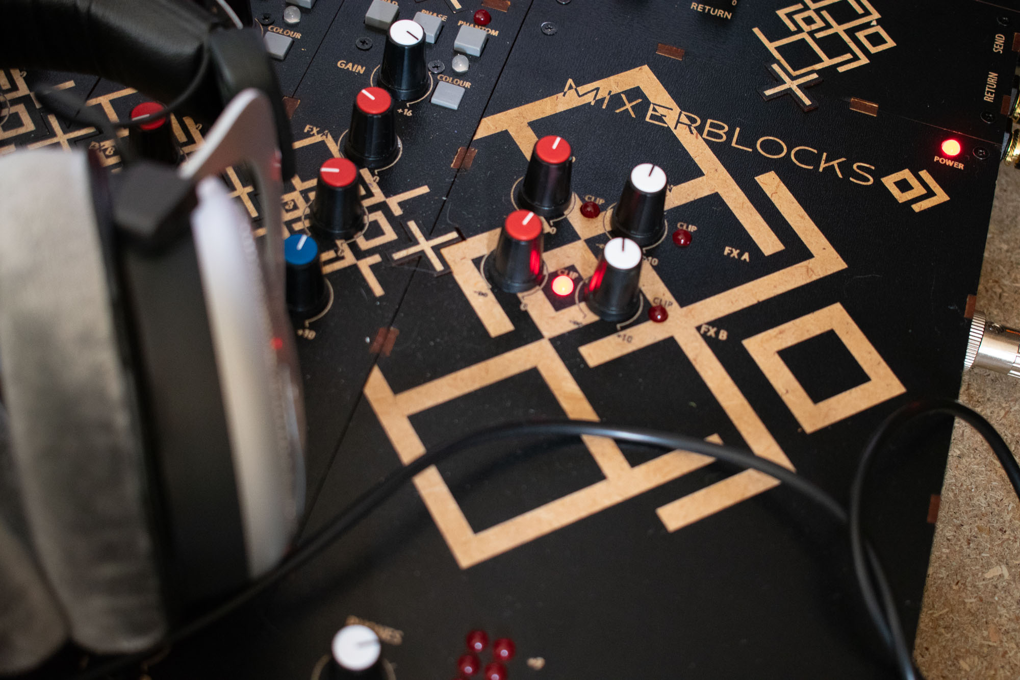
Mixerblocks Main Docking Block
one dock to route them all
The Docking Block helps connect all the signals from the channels and routes them as needed. This block contains:
- The power supply connector (+/- 15V and 48V phantom), these voltages power the dock’s circuits and gets distributed to the channels to power them up as well;
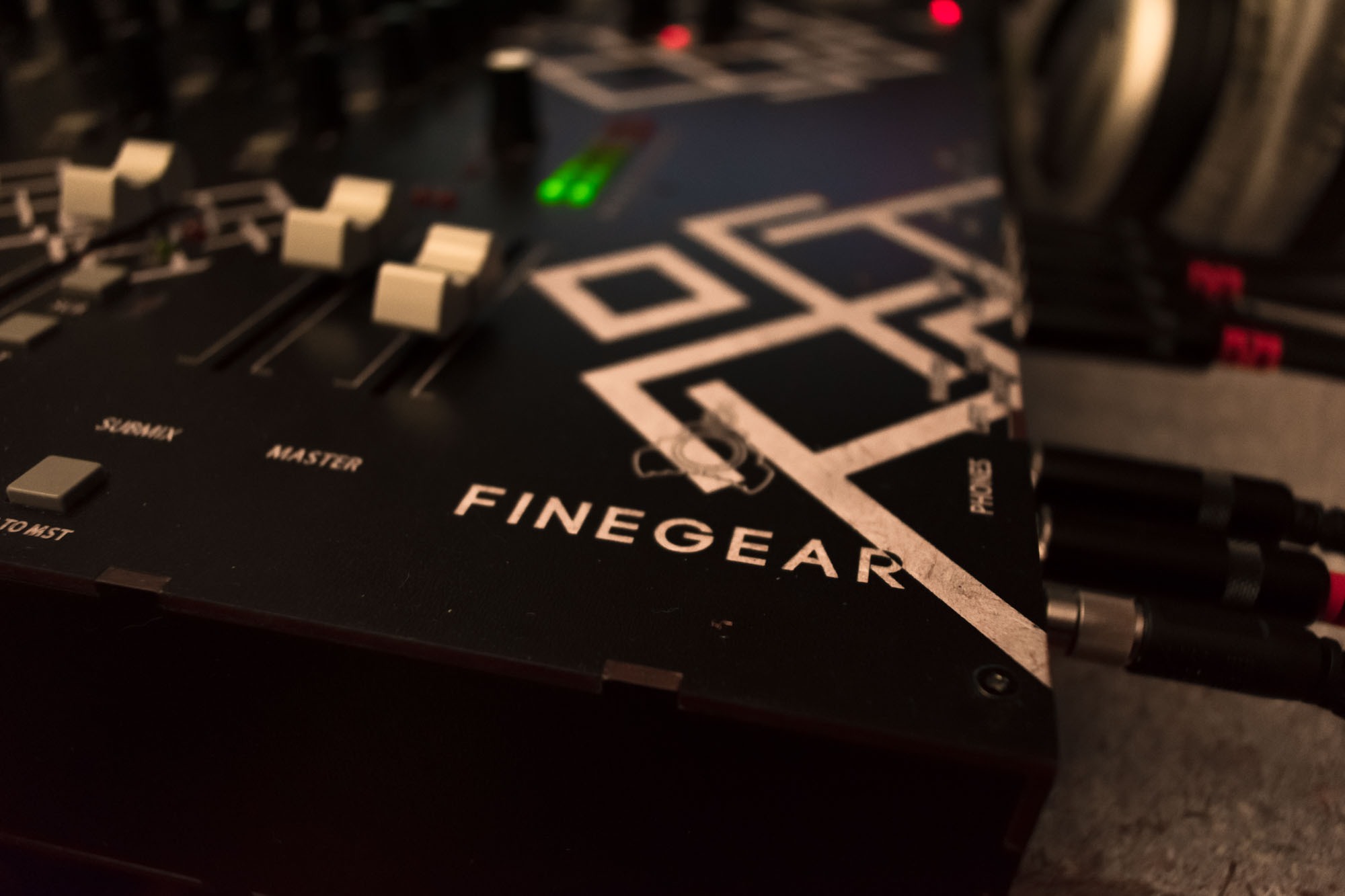
- The stereo master mix bus, fader amp and balanced outputs, with inserts;
- The stereo submix bus, fader amp and balanced outputs with inserts;
- Two effect send output amps and their respective balanced outputs;
- Two effect returns with balanced inputs and input preamps;
- A phones output amplifier with solo mechanism;
- An Extra Blocks connector which allows mixing in additional signal from extra-blocks connected at the back of the docking block (more info soon);
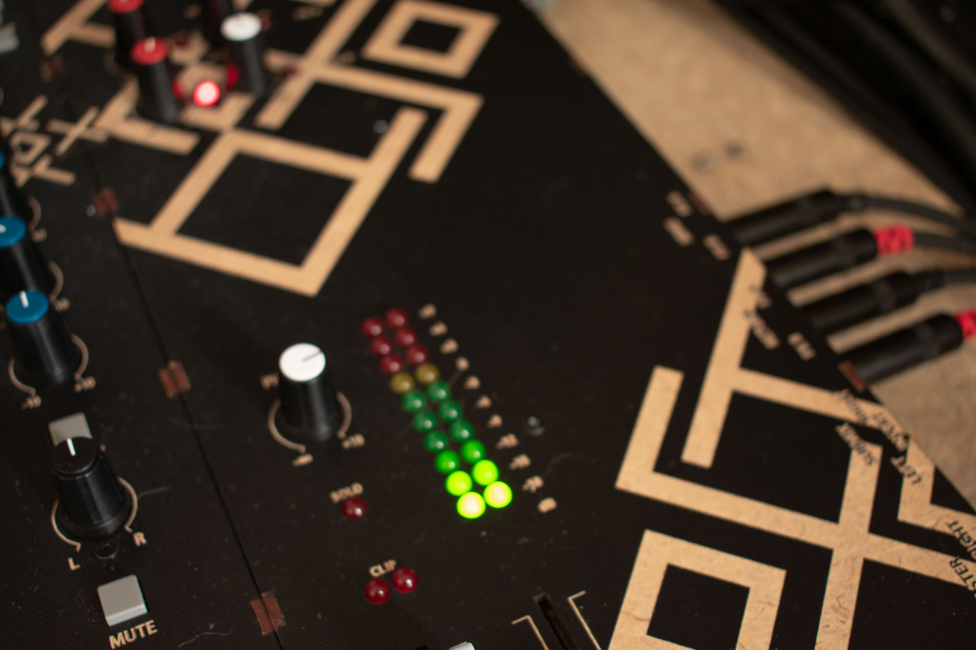
- A stereo 10 LED vuMeter for the master output bus;
- Clipping LEDs for all the faders and knobs (submix, effects sends and returns) for a better visualisation of the signals passing through the dock;
- A connector on the left side which connects to the first channel, containing power pins to power the connected channels as well as the pins for the different buses to which the channels add their signals (master, submix, solo, and effect sends A&B).
Contact us order yours now!
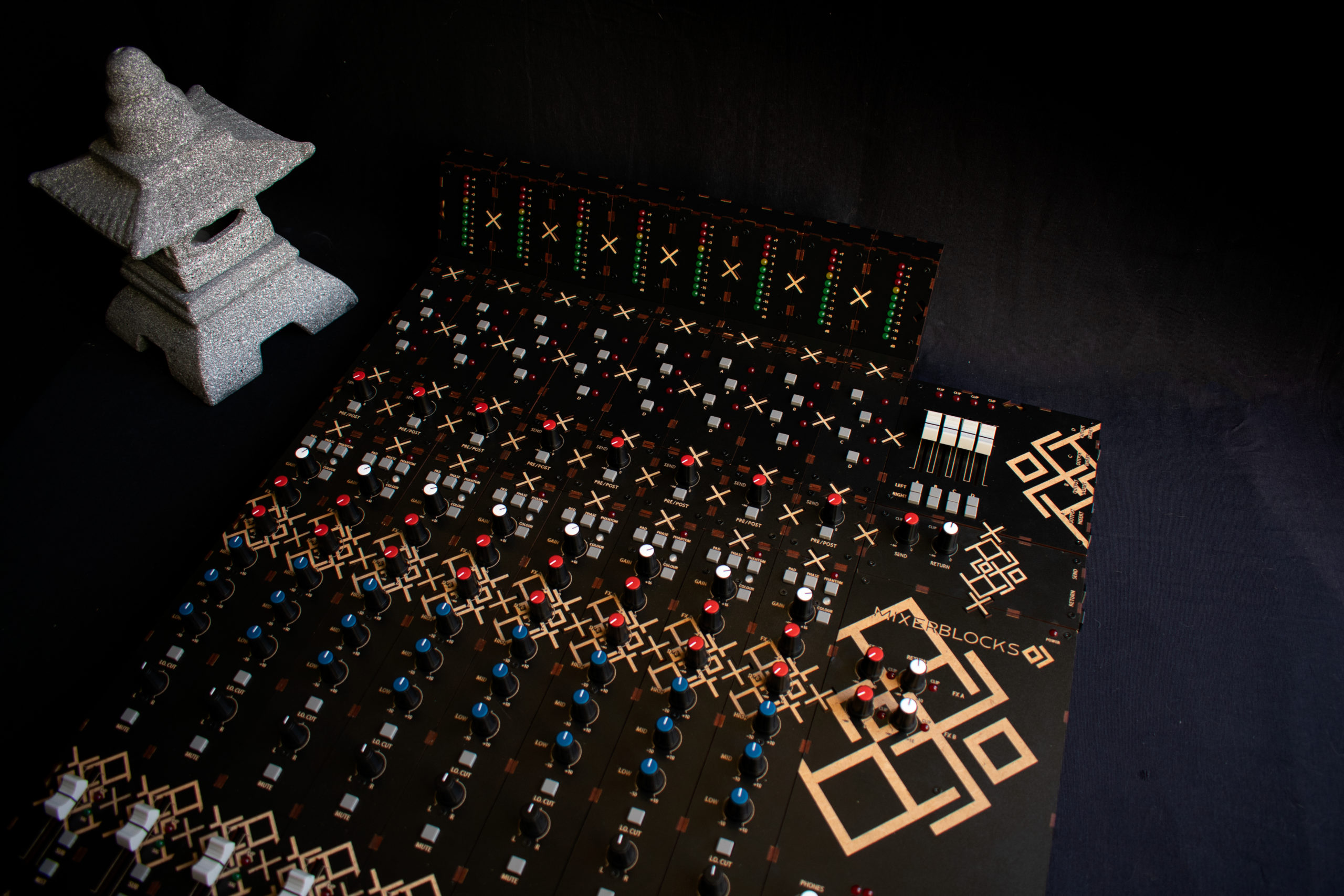
Analog powerhouse
The central block for any Mixerblocks console, it powers the channels and it sums up the signals and sends them to the (balanced) outside world. The signals routed by the docking block are:
- master mix,
- submix,
- two effect sends,
- their two respective effect returns,
- a solo bus (for the phones output)
- the incoming signals from the extra blocks.
The master and the submix buses also have effect inserts and balanced outputs. A stereo 10 segment LED vuMeter helps visualise the output signal while strategically placed clipping LEDs indicate if any signal saturates. The connected channels have to be connected to a dock.


TECHNICAL SPECIFICATIONS
- Current draw: max 0.35 A
- SNR: -93 dB
- Input impedance:
FX return: 32k Ω unbalanced, 64 kΩ balanced - Output impedance:
Main mix putput: 70 Ω unbalanced, 140 Ω balanced,
Submix output: 70 Ω unbalanced, 140 Ω balanced,
Effect send outputs: 70 Ω unbalanced, 140 Ω balanced,
Phones output: 30 Ω. - Crosstalk (at 1kHz):
Master down: -70 dB
- Frequency response:
Input to main: 20-20 kHz, +0/-0.5 dB
Input to submix: 20-20 kHz, +0/-0.5 dB
Input to effect sends: 20-20 kHz, +0/-0.5 dB - Master fader amp gain: -60 dB … +10 dB
- Submix fader amp gain: -60 dB … +10 dB
- Phones amp gain: -60 dB … +10 dB
- FX return amps gain: -60 dB..+10 dB
- LED vuMeter: 3 dB/LED pair
- Dimensions (W x H x D): 145 mm x 63 mm x 400 mm
- Weight: 970 g
SIGNAL PATH

EXTRA BLOCKS

Some types of extra blocks for channels have to be connected to their specific type’s Docking block which mixes and routes the signals and sends/adds them to the Master Mix bus.
For example, the Extra Effect Send and Extra Submixes Channel blocks must be connected to their corresponding docking block. Each specific docking block has specific functions.
The Extra Effect Send Docking block:
- outputs the mixed send signals from the channels to the effect send output jack,
- retrieves and amplifies the processed signal from the return input jack and
- mixes the return signal to the master bus.
The Extra Submixes Docking block:
- mixes the channels’ signals into the 4 extra buses,
- amplifies each bus ,
- passes each bus signal through an insert jack,
- supplies a balanced output for each bus,
- routes the buses to the left or right channel of the master bus.
DOCUMENTATION
Coming soon!
- Docking block manual
- Docking block ass’y manual
- Docking block enclosure ass’y manual
- Docking block DIY ressources
